|
|
================================== Rev 1.06 - 2022/03/25
This tool helps you to find the workpiece zero point for X, Y, & Z. Whenever the zero point is mentioned, the workpiece zero point is always implied. The EdgeFinder and tool offsets are removed from the displayed DRO (Digital Read Out) values.
(a) Command 999 - opens this document.
(b) All functions can be canceled by entering the number zero or pressing 'enter' to a blank line. Once a command has been started, it can be aborted by pressing Mach3 STOP or E-STOP.
(c) The command input consists of a 1, 2, or 3 digit number.
(d) X-Min or Y-Min is the side of the workpiece that will have the lowest X or Y position value.
This is usually what is set to X=0.0000 or Y0.0000.
(e) X-Max or Y-Max is the side of the workpiece that will have the largest X or Y position value.
This is used mostly for workpiece size information, and is usually not set to zero.
(f) Z-Top is the top of the workpiece as referenced from the Edge-Finder or the workpiece itself. The offset to Z0 depends on the height of the touch surface above the Workpiece surface.
The workpiece top surface normally becomes Z0.0000.
(g) Most of the Edge-Finder functions can be accomplished in several different ways.
In general, the single digit functions are the primary functions,
and they ask the operator additional questions for EdgeFinder offset and tool size before begining.
The two digit functions from 11 to 16 are the inverse of the primary functions 1 to 6.
For example, FCN-2 finds X-MIN and sets that edge to zero (X0). FCN-12 finds X-MIN and reports its position with respect to the current X0.
Another example, FCN-4 finds X-MAX and reports its position with respect to X0, where FCN-14 finds X-MAX and sets that edge to zero (X0).
The remaining two digit commands (17, 27, 37) offer speed access to a function and assume default values for offset and tool diameter. These commands start immediately after pressing 'enter'. Default values can be user modified only in the HiddenScript code.
The three digit commands offer speed access to a function where the second and third digits select the desired offset and tool diameter respectively. These commands start immediately after pressing 'enter'. See FCN-99 for details.
Note: If any of these Edge-Finder functions do not perform as described, please email cnc@vancura.biz and explain.
==================================
How this program progressed:
Functions 1, 2, 3, 6, 14, & 15 set either X, Y, or Z to zero. Functions 12, 13, 4, 5 measure the offset from the current zero position.
1) The original concept was to find and set X, Y, or Z to zero (FCN 1, 2, 3, & 6 were created).
2) Then I decided I wanted to be able to measure how big the workpiece is (Fcn 4 & 5).
3) Then I decided that somebody might want to set X-Max and Y-Max to zero (Fcn 14 & 15).
4) Then why not measure to X-Min and Y-Min from zero (Fcn 12 & 13)
5) Then there was a request for commands that ran without asking questions (Fcn 17, 27, & 37)
6) Then I decided to try a 3 digit command set, with built-in options that ran without questions. (Fcn 100 – 800).
And this is it.
Return to top
==================================
FCN 1
Find Center of Hole; Set X=0, Y=0
This routine uses the Edge-Finder corner hole and to find the
Work-Piece corner Z0, X0, & Y0
(a) Place the Edge-Finder on the work-piece corner nearest X0 and Y0.
Note: Diameter of Probe need not be known.
(b) Position the probe about 0.10 inch (2.5mm) into the corner hole,
making sure the probe is not touching the edge of the hole or the work-piece.
(c) Select Function 1 and then ENTER.
The Probe will search for the edges of the hole and
calculate the center of the hole. The Edge-Finder hole is located directly over
the corner of X0 and Y0.
The function will set X & Y to zero. Make sure the probe is above the
Edge-Finder before moving either X or Y.
(c) Return Values: Center of hole = X0.000, Y0.000, Z=Unchanged.
Return to top
==================================
FCN 2
Find X-Min Edge; Set X=0
Note:
This function asks if you are measuring to the Edge-finder or the work-piece.
If the work-piece is the target, it must be a conductive metal, and properly
connected to the probe circuit.
Note: This function requires you to use a probe of a known diameter
You can select either a fixed diameter or a custom diameter.
(a) Place the Edge-Finder on the work-piece corner nearest X-Min.
(b) Position the probe less than 1 inch
(25mm) from the X-Min edge and about 0.10 inch (2.5mm) below the top surface of
your target, making sure the probe is not touching the edge.
(c) Select Function 2, select tool diameter, select Edge-Finder or
work-piece, and
(d) then ENTER.
The Probe will search for the X surface of the target and calculate the X0
position.
The function will set X to zero.
Make sure the probe is above the Edge-Finder before moving either X or Y.
(e) Return Values: X = 0.000, Y & Z = unchanged.
Note: The maximum search distance is 1 in. (25.4mm)
Return to top
==================================
FCN 3
Find Y-Min Edge; Set Y=0
Note: This function asks if you are measuring to the Edge-finder or the work-piece.
If the work-piece is the target, it must be a conductive metal, and properly
connected to the probe circuit.
Note: This function requires you to use a probe of a known diameter
you can select either a fixed diameter or a custom diameter.
(a) Place the Edge-Finder on the work-piece corner nearest Y-Min.
(b) Position the probe less than 1 inch (25mm) from the Y-Min edge,
and about 0.10 inch (2.5mm) below the top surface of
your target, making sure the probe is not touching the edge.
(c) Select Function 3, select tool diameter, select Edge-Finder or
work-piece, and
(d) then ENTER.
The Probe will search for the Y surface of the target and calculate the Y0
position.
The function will set DRO Y to zero.
Make sure the probe is above the Edge-Finder before moving either X or Y.
(e) Return Values: Y = 0.000, X & Z = unchanged.
Note: The maximum search distance is 1 in. (25.4mm)
Return to top
==================================
FCN 4
X-Max Edge Offset from X0
Note:
This function asks if you are measuring to the Edge-finder or the work-piece.
If the work-piece is the target, it must be a conductive metal, and properly
connected to the probe circuit.
Note: This function requires you to use a probe of a known diameter. You
can select either a standard diameter or a custom diameter.
(a) Place the Edge-Finder on the work-piece corner nearest X-Max.
(b) Position the probe less than 1 inch (25mm) from the X-Max edge,
and about 0.10 inch (2.5mm) below the top surface of the targe edge,
making sure the probe is not touching the edge.
(c) Select Function 4, select tool diameter, select Edge-Finder or
work-piece, and
(d) then ENTER.
The Probe will search for the X-Max surface of the target and calculate the X-Max
position.
The function will display X-Max on the DRO.
Make sure the probe is above the Edge-Finder before moving in either X or Y direction.
(e) Return Values: Y & Z = unchanged. X-Max = Offset from X0.
Note: The maximum search distance is 1 in. (25.4mm)
Return to top
==================================
FCN 5
Y-Max Edge Offset from Y0
Note: This function asks if you are measuring to the Edge-finder or the work-piece.
If the work-piece is the target, it must be a conductive metal, and properly
connected to the probe circuit.
Note: This function requires you to use a probe of a known diameter
You can select either a fixed diameter or a custom diameter.
(a) Place the Edge-Finder on the work-piece corner nearest Y-Max.
(b) Position the probe less than 1 inch (25mm) from the Y-Max edge,
and about 0.10 inch (2.5mm) below the top surface of
your target, making sure the probe is not touching the edge.
(c) Select Function 5, select tool diameter, select Edge-Finder or
work-piece, and
(d) then ENTER.
The Probe will search for the Y surface of the target and calculate the Y-Max
position.
The function will display Y-Max on the DRO.
Make sure the probe is above the Edge-Finder before moving either X or Y.
(e) Return Values: X & Z = unchanged. Y-Max = Offset from Y0.
Note: The maximum search distance is 1 in. (25.4mm)
Return to top
==================================
FCN 6
Find Z-Top surface; Set Z=0
Note:
This function asks if you are measuring to the Edge-finder or the work-piece.
If the work-piece is the target, it must be a conductive metal, and properly
connected to the probe circuit.
(a) Place the Edge-Finder on the work-piece corner nearest X & Y
Zero.
(b) Position the probe less than 1 inch
(25mm) from the top surface, making sure the probe is not touching the surface.
(c) Select Function 6, select Edge-Finder or work-piece, and
(d) then ENTER.
The Probe will search for the Z surface of the target and calculate the Z0
position.
Make sure the probe is above the Edge-Finder before moving either X or Y.
(e) Return Values: X & Y = unchanged. Z= 0.000 at surface.
Note: The maximum search distance is 1 in. (25.4mm)
Return to top
==================================
FCN 7
Find Z0, X0, Y0 Edge /With options & Set XYZ=0
Function 7
is the manual setup for find X Y & Z. The options include using either the
Edge-Finder or the Work-Piece. The Tool diameter must be known where you can
select one of the standard diameters or enter a custom tool diameter.
(a) Place the Edge-Finder over the work-piece corner near X0 and Y0.
(b) Position the probe over the Edge-Finder avoiding the holes in the
edge-finder, making sure the probe is not touching the edge finder or the
work-piece.
Note: The probe should be less than 3/4in (20mm) from the Z, X, & Y corner.
(c) Select Function 7, then ENTER.
(d) Select either the touch to Work-Piece or Edge-Finder option, Then
ENTER.
(e) Select The correct probe diameter, then ENTER.
(f) Select The surface offset for Z-zero, then ENTER.
The Probe will first locate the top surface and set
Z-zero. Second it will find the X surface and the Y Surface, and set both X
& Y to work-piece zero.
Make sure the probe is at a safe height before moving either X or Y.
(g) Return Values: Work-piece X0=0.000, Y0=0.000, Z0=0.000.
Return to top
==================================
FCN 8
& 80x: Quick Find Z0, X0, Y0 with Edge-Finder-Hole; Set ZXY=0
Function 8 uses the Edge-Finder small corner hole to find the Work-Piece corner X0, Y0.
Z0 = top of edgefinder.
Return Values: Work-piece X0=0.000, Y0=0.000, Z0=Top of Edgefinder.
Digit definitions for Function 8xx:
(b) Second Digit: Selects Z zero offset.
0 = default = option 1
1 = default Z0= touch depth (Top of edgefinder)
2 = default Z0= touch depth minus Z_TOP1 (~0.150" or 3.71mm)
3 = default Z0= touch depth minus Z_TOP2 (~0.250" or 6.35mm)
(c) Third Digit: Selects hole to use for measurement:
0 = Default hole = option 1
1 = Small corner hole.
2 = Large hole.
Return Values: Work-piece X0=0.000, Y0=0.000, Z0=Selected depth below top of edgefinder.
By using your best practice settings, the function
requires only entering one command to find X0, Y0, & X0.
(a) Place the Edge-Finder snugly on the X0 Y0 work-piece corner.
(b) Position the probe approximately centered
over the Edge-Finder corner hole, making sure the probe is not touching the
edge finder or the work-piece. The probe should be less than 3/4in (20mm) above
the Edge-finder and not below the surface.
(c) Select the desired function 8 or 8xx then ENTER. The operation will begin immediately.
The Probe will:
(1) Raise a little, move to one side (plus X),
locate the top surface, and set Z-zero.
(2) Return to and Descend into the hole about 0.1-in. (2.5mm), and find the X and Y hole center.
(3) And finally, set both X & Y to work-piece zero.
Make sure the probe is at a safe height before moving either X or Y.
Return to top
==================================
FCN 11
Find Center of Hole Offset from X0,Y0
This routine uses the Edge-Finder corner hole and to find the
Work-Piece corner Z0, X0, & Y0
(a) Place the Edge-Finder on the work-piece corner nearest X0 and Y0.
Note: Diameter of Probe need not be known.
(b) Position the probe about 0.10 inch (2.5mm) into the corner hole,
making sure the probe is not touching the edge of the hole or the work-piece.
(c) Select Function 1 and then ENTER.
The Probe will search for the edges of the hole and
calculate the center of the hole. The Edge-Finder hole is located directly over
the corner of X-Min and Y-Min.
The DRO will show X-Min & Y-Min as offsets from X0 & Y0.
Make sure the probe is above the Edge-Finder before moving either X or Y.
(d) Return Values: Center of hole = Offset from X0 and Y0, Z=Unchanged.
Return to top
==================================
FCN 12
Find X-Min Edge Offset from X0
Note:
This function asks if you are measuring to the Edge-finder or the work-piece.
If the work-piece is the target, it must be a conductive metal, and properly
connected to the probe circuit.
Note: This function requires you to use a probe of a known diameter
You can select either a standard diameter or a custom diameter.
(a) Place the Edge-Finder on the work-piece corner nearest X-Min.
(b) Position the probe less than 1 inch
(25mm) from the X-Min edge and about 0.10 inch (2.5mm) below the top surface of
your target, making sure the probe is not touching the edge.
(c) Select Function 12, select tool diameter, select Edge-Finder or
work-piece, and
(d) then ENTER.
The Probe will search for the X surface of the target and calculate the X-min
position.
The function will display X-Min, on the DRO, as an offset from X0.
Make sure the probe is above the Edge-Finder before moving either X or Y.
(e) Return Values: X = Offset from X0; Y, & Z = unchanged.
Note: The maximum search distance is 1 in. (25.4mm)
Return to top
==================================
FCN 13
Find Y-Min Edge Offset from Y0
Note:
This function asks if you are measuring to the Edge-finder or the work-piece.
If the work-piece is the target, it must be a conductive metal, and properly
connected to the probe circuit.
Note: This function requires you to use a probe of a known diameter
You can select either a fixed diameter or a custom diameter.
(a) Place the Edge-Finder on the work-piece corner nearest Y-Min.
(b) Position the probe less than 1 inch (25mm)
from the Y-Min edge and about 0.10 inch (2.5mm) below the top surface of your
target, making sure the probe is not touching the edge.
(c) Select Function 13, select tool diameter, select Edge-Finder or
work-piece, and
(d) then ENTER.
The Probe will search for the Y surface of the target and calculate the Y-Min
position.
The function will display Y-Min, on the DRO, as an offset from Y0.
Make sure the probe is above the Edge-Finder before moving either X or Y.
(e) Return Values: Y = Offset from Y0, & Z = unchanged.
Note: The maximum search distance is 1 in. (25.4mm)
Return to top
==================================
Note:
This function asks if you are measuring to the Edge-finder or the work-piece.
If the work-piece is the target, it must be a conductive metal, and properly
connected to the probe circuit.
Note: This function requires you to use a probe of a known diameter
You can select either a fixed diameter or a custom diameter.
(a) Place the Edge-Finder on the work-piece corner nearest X-Max.
(b) position the probe less than 1 inch (25mm) from the X-Max edge,
and about 0.10 inch (2.5mm) below the top surface of
your target, making sure the probe is not touching the edge.
(c) Select Function 14, select tool diameter, select Edge-Finder or
work-piece, and
(d) then ENTER.
The Probe will search for the X surface of the target and calculate the X-Max
position.
The function will display X-Max = 0.0000, on the DRO.
Make sure the probe is above the Edge-Finder before moving either X or Y.
(e) Return Values: X-Max = 0.000, Y & Z = unchanged.
Note: The maximum search distance is 1 in. (25.4mm)
Return to top
==================================
Note:
This function asks if you are measuring to the Edge-finder or the work-piece.
If the work-piece is the target, it must be a conductive metal, and properly
connected to the probe circuit.
Note: This function requires you to use a probe of a known diameter
You can select either a fixed diameter or a custom diameter.
(a) Place the Edge-Finder on the work-piece corner nearest Y-Max.
(b) Position the probe less than 1 inch
(25mm) from the Y-Max edge and about 0.10 inch (2.5mm) below the top surface of
your target, making sure the probe is not touching the edge.
(c) Select Function 15, select tool diameter, select Edge-Finder or
work-piece, and
(d) then ENTER.
The Probe will search for the Y surface of the target and calculate the Y-Max
position.
The function will display Y-Max = 0.0000, on the DRO.
Make sure the probe is above the Edge-Finder before moving either X or Y.
(e) Return Values: Y-Max = 0.000, X & Z = unchanged.
Note: The maximum search distance is 1 in. (25.4mm)
Return to top
==================================
FCN16
Find Z-Top surface Offset from Z0.
Note:
This function asks if you are measuring to the Edge-finder or the work-piece.
If the work-piece is the target, it must be a conductive metal, and properly
connected to the probe circuit.
(a) Place the Edge-Finder on the work-piece corner nearest X & Y
Zero.
(b) Position the probe less than 1 inch
(25mm) from the top surface, making sure the probe is not touching the surface.
(c) Select Function 16.
(d) Select Edge-Finder or work-piece, and then ENTER.
The Probe will search for the Z surface of the target and calculate the Z0
position.
Make sure the probe is above the Edge-Finder before moving either X or Y.
(e) Return Values: Z = Surface offset from Z0; X & Y = Unchanged.
Caution: The probe will be left touching the surface. Raise UP the Z axis before moving X or Y.
Return to top
==================================
FCN 17
Quick Find Z0, X0, Y0 To Work-Piece; Set ZXY=0
This
routine finds the Work-Piece corner Z, X, & Y using your default settings.
By using your best practice settings, the function requires only entering one
command to find X0, Y0, & X0.
Note: The Work-Piece must be conductive and connected to the probe circuit.
(a) Position the probe over the work-piece corner nearest X0 and Y0. The
probe should be less than 3/4in (20mm) from the Z, X, & Y corner.
(b) Select Function 17, then ENTER. The
operation will begin immediately.
The Probe will first locate the top surface and set
Z-zero. Second it will find the X surface and the Y Surface, and set both X
& Y to work-piece zero.
Make sure the probe is at a safe height before moving either X or Y.
(c) Return Values: Work-piece X0=0.000, Y0=0.000, Z0=0.000.
Return to top
==================================
FCN 27
Quick Find Z0, X0, Y0 To Edge-Finder; Set ZXY=0
This
routine uses the Edge-Finder and your default settings to find the Work-Piece
corner Z0, X0, & Y0
By using your best practice settings, the function
requires only entering one command to find X0, Y0, & X0.
(a) Place the Edge-Finder snugly on the X0 Y0 work-piece corner.
(b) Position the probe over the Edge-Finder avoiding the holes in the
edge-finder, making sure the probe is not touching the edge finder or the
work-piece. The probe should be less than 3/4in (20mm) from the Z, X, & Y
corner.
(c) Select Function 37, then ENTER. The operation will begin immediately.
The Probe will first locate the top surface and set
Z-zero. Second it will find the X surface and the Y Surface. And finally, set
both X & Y to work-piece zero.
(c) Return Values: Work-piece X0=0.000, Y0=0.000, Z0=0.000.
Return to top
==================================
FCN 37
Quick Find Z0, X0, Y0 To Edge-Finder-Hole & Set ZXY=0
This
routine uses the Edge-Finder corner hole and your default settings to find the
Work-Piece corner Z0, X0, & Y0
By using your best practice settings, the function
requires only entering one command to find X0, Y0, & X0.
(a) Place the Edge-Finder snugly on the X0 Y0 work-piece corner.
(b) Position the probe approximately centered
over the Edge-Finder corner hole, making sure the probe is not touching the
edge finder or the work-piece. The probe should be less than 3/4in (20mm) above
the Edge-finder and not below the surface.
(c) Select Function 37, then ENTER. The
operation will begin immediately.
The Probe will first move to one side (plus X) and
locate the top surface and set Z-zero. Second it descend
into the hole about 0.1-in. (2.5mm) and find the X and Y hole
center. And finally, set both X & Y to work-piece zero.
Make sure the probe is at a safe height before moving either X or Y.
(d) Return Values: Work-piece X0=0.000, Y0=0.000, Z0=0.000.
Return to top
==================================
FCN 99
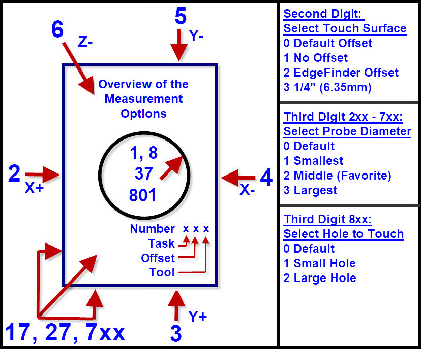
Three Digit (100-833) One Step Setups & Set 0
By using one three digit number it is possible to select all possible edge finding
combinations. One or two combinations will stand out as a best fit your needs.
Note: this command starts immediately after ENTER
Digit definitions:
(a) First Digit: Range: 1 to 7; (for FCN-8 see g below) Same purpose as single digit functions listed in the above chapters.
(b) Second Digit: Touch Surface Offsets: Range 0 to 3:
0 = Default surface = option 1)
1 = Direct to work-piece surface Offset
2 = to EdgeFinder Low Top Surface (~0.150" or 3.81 mm)
3 = to EdgeFinder High Top Surface (~0.250" or 6.35 mm)
4-9 = to Default Surface Offset
(c) Third Digit: Tool/Probe diameter Select: Range 0 to 3:
0 = Default Tool = option #2
1 = Tool #1 (smallest)
2 = Tool #2 (Middle , default)
3 = Tool #3 (largest)
4-9 = Default Tool
(d) Usage: To find the corner X0
Place EdgeFinder on corner of workpiece
Enter first digit '2'
to use the EdgeFinder; second digit = 2
and to use a 1/4" (6.35mm) tool as the probe; Enter third digit '3'.
The resulting Value 223 would select function 2,
the edgefinder, and the large sized tool.
(e) The full operation of the different functions are discussed in the chapters above.
(f) The default values are modifiable, however the process requires some minimal
knowledge of BASIC. There is no need for a compiler or special tools.
Everything that is needed is built into Mach3 under Operator/Edit Button Script.
(If you can read, type, open a text document, and save it, you can do it.)
(g) FCN-8xx has special rules.
FCN-8 requires the use of an edgefinder with the hole in it.
Digit definitions for Function 8xx:
- Second Digit: Selects Z zero offset. Same as above.
0 = Default = option 1
1 = Direct to work-piece surface (Caution: Must have hole in workpiece)
2 = Touch depth minus Z_TOP1 (~0.150" or 3.71mm) (Finder on corner of workpiece)
3 = Touch depth minus Z_TOP2 (~0.250" or 6.35mm) (Finder on middle of workpiece)
- Third Digit: Selects hole to use for measurement:
0 = Default hole = option 1
1 = Small corner hole.
2 = Large hole Offset 0.5" (12.7mm).
Position the probe approximately centered over the Edge-Finder corner hole,
making sure the probe is not touching the edge finder or the work-piece.
The probe should be less than 3/4in (20mm) above
the Edge-finder and not below the Edge-Finder surface.
Note: The most common 8xx Command would be 821.
Return to top
==================================